Warning: file_exists(): open_basedir restriction in effect. File(/views/templates/hook/tab.tpl) is not within the allowed path(s): (/home/fhamradi/:/opt/cpanel/ea-php81/root/usr:/usr/local/lib/php:/tmp:/etc/pki/tls/certs/ca-bundle.crt:/var/cpanel/php/sessions:/usr/local/bin/wp) in /home/fhamradi/public_html/classes/module/Module.php on line 2292 Reviews
Description
2x5/8 λ VHF collinear vertical antenna tunable from 50 to 54 MHz with calibration table.
Antenna also configurable in short 5/8 λ version with whip length adjustment graph.
Extremely robust construction in AW6063-T66 aluminum alloy.
Supplied with quality 304 and 316 stainless steel screws for long rust-free service.
The Ground plane made with 4 full Quarter Wave radials.
High applicable input power, up to 2Kw continuous All-mode.
Detailed assembly manual and serial number identifying the production batch and construction data.
Electrical Data
Mechanical Data
Type
2x5/8 λ GP collinear with 4 ¼ wave radials
Materials
Cold drawn tube in AW6063-T66 Aluminum alloy, Fiberglass, Brass, PTFE. All screws in AISI-304 and 316 stainless steel
Frequency Range
Tunable from 50 to 54 MHz (supplied with graph)
Surface in the wind
0.195m 2
Impedance
50Ω Unbalanced
Load @ 130Km/h
19Kgf
Radiation (H Plane)
Omnidirectional
Wind resistance (without ice)
130 km/h
Radiation (E Plane)
Beamwidth @ -3dB = 30°
Total Height
8.12m at 50MHz
polarization
Linear – Vertical
Radiator Length
7.6m at 50MHz
I earn
3.5dBd – 5.65dBi
Radial Length
1.4m (quarter wave)
Bandwidth at 2:1 SWR
≥ 2.6MHz @ 50MHz
Mounting pole
ø 40-54 mm
SWR in resonance
≤1.2:1 typical <1.1:1
Net Weight
4.30 kg
Max applicable power
2000 Watts continuous all modes of output
Packaging Dimensions
14x14x145 cm
Diet
High “Q” air match coil connected to ground in DC
Weight in package
5.4Kg
Connector
UHF female 50Ω with PTFE insulator, gold plated center pin
Materials and Construction
For our tubes we have used the best alloy available for the construction of antennas, the AW6063-T66 alloy of Aluminum, Magnesium and Silicon tempered to the T-66 state which gives the stylus exceptional resistance, which is achieved by extrusion and subsequently cold drawn. Our tubes are extremely precise on both diameters, and also on the thickness of the wall, allowing for precise coupling and with less “play” between the tubes.
The “Ground Plane” is composed of 4 sturdy radials of length 1.4m, “Full-Quarter Wave” made of single section tube with diameter and thickness respectively 13×1.25mm which are fixed to the support plate by means of two U-Bolts and self-locking nuts. In the fixing area 4 fiberglass reinforcements are provided which strengthen the joints and prevent the crushing of the tubes.
Technical choices that make the difference
Why make an antenna capable of withstanding continuous power of 2Kw?
Because an antenna that accepts high power is a more efficient antenna, otherwise it would tend to heat up due to the Joule effect and dissipate a significant part of the applied RF power into heat, which happens with most competing products, but which unfortunately users cannot test due to a lack of adequate equipment and instrumentation.
The high "Q" coil
The coil plays a fundamental role in impedance matching and maximum RF transfer. Its shape, given by the length/diameter ratio, the pitch between the turns, the material and diameter of the wire and the presence or absence of metal cores inside it, determine its quality factor “Q” (“Q” = Quality factor).
In simple terms the higher the “Q” of the coil the lower the high frequency losses. We have created a generously sized coil suspended in air without metal cores, with widely spaced turns obtaining one of the highest “Q” values.
This translates into maximum efficiency, and the ability to handle high RF power. In addition, the coil is directly connected to DC-Ground, so atmospheric disturbances and background noise are significantly reduced.
The UHF Connector
The connector is not a commercial SO-239 type as used by most manufacturers. The connector has been designed and manufactured directly by us, has a real impedance of 50 Ohm and can be used up to 500MHz. We have created a reliable connector that can handle the transit of 5Kw CW continuous at 30MHz and more than 3Kw at 50MHz.
The body is made of nickel-plated CW614N brass, while the pin is plated in 24K gold to avoid oxidation and is equipped with a 4-fin insulator that maintains its centering and elasticity, avoiding contact losses.
The insulating part is made of PTFE, one of the best insulating materials for its exceptional electrical (low dielectric constant and reduced loss factor) and thermal (operating temperature from -100° to +260°) properties. Finally, the connector is protected by a special elastomer cap that prevents water and humidity infiltration.
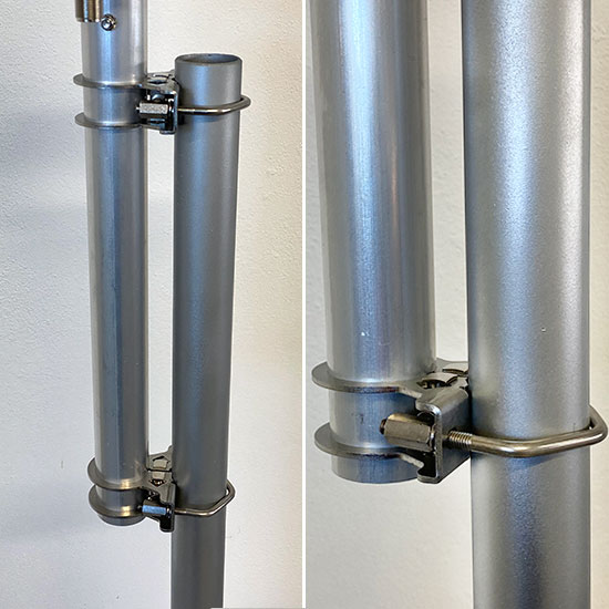
The Anchor Bracket
Made of 2.5 mm thick AISI304 stainless steel, it is fixed to the antenna tube using a clamp locking system, creating an extremely robust mechanical lock.
The fixing to the mast is made with M6 V-Bolts in AISI304 and column nuts to facilitate tightening.
Warning: file_exists(): open_basedir restriction in effect. File(/views/templates/hook/posproductcomments.tpl) is not within the allowed path(s): (/home/fhamradi/:/opt/cpanel/ea-php81/root/usr:/usr/local/lib/php:/tmp:/etc/pki/tls/certs/ca-bundle.crt:/var/cpanel/php/sessions:/usr/local/bin/wp) in /home/fhamradi/public_html/classes/module/Module.php on line 2292


 No review at the moment