Warning: file_exists(): open_basedir restriction in effect. File(/views/templates/hook/tab.tpl) is not within the allowed path(s): (/home/fhamradi/:/opt/cpanel/ea-php81/root/usr:/usr/local/lib/php:/tmp:/etc/pki/tls/certs/ca-bundle.crt:/var/cpanel/php/sessions:/usr/local/bin/wp) in /home/fhamradi/public_html/classes/module/Module.php on line 2292 Reviews
Description
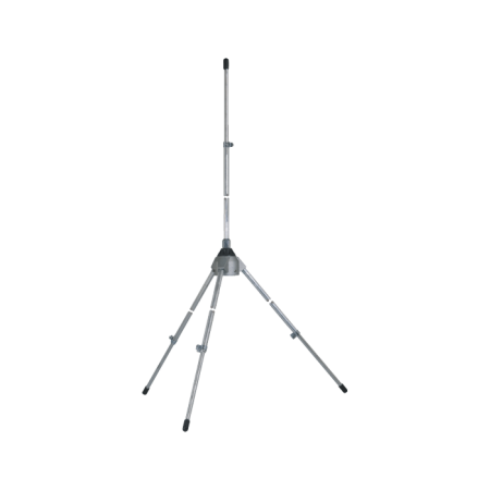
Grazioli FE10V is a 5/8 λ antenna for the 10 or 11m band. The goal was to build an extremely robust, high-performance antenna with a low radiation angle that could handle extremely high power (5Kw CW continuous all-mode). The result is FE10V, which has unique features compared to the current market and gathers all our experience in the sector.
Electrical Data
Mechanical Data
Type
5/8 λ GP with 4 ¼ wave radials
Materials
Cold drawn tube in AW6063-T66 Aluminum alloy, Fiberglass, Brass, PTFE. All screws in AISI-304 and 316 stainless steel
Frequency Range
Tunable from 26 to 30 MHz (supplied with graph)
Surface in the wind
0.29m 2
Impedance
50Ω Unbalanced
Load @ 130Km/h
280N – 28.5Kgf
Radiation
Omnidirectional
Wind resistance (without ice)
130 km/h
polarization
Linear – Vertical
Total Height
7.63mA 26MHz
I earn
1.5dBd – 3.65dBi
Radial Length
2.7m (quarter wave)
Bandwidth at 2:1 SWR
≥ 1.4MHz @ 26MHz to ≥ 1.6MHz @ 30MHz
Mounting pole
ø 40-54 mm
SWR in resonance
≤1.2:1 measured at connector
Net Weight
6 Kg
Max applicable power
5000 Watts continuous all modes of output
Packaging Dimensions
14x14x145 cm
Diet
High “Q” air match coil connected to ground in DC
Weight in package
7.3Kg
Connector
UHF female 50Ω with PTFE insulator, gold plated center pin
Materials and Construction
For our tubes we have used the best material available for the construction of antennas; it is the alloy of Aluminum, Magnesium and Silicon called AW6063-T66, tempered to the T-66 state. It gives the stylus an exceptional resistance, which is achieved by extrusion and subsequently by cold drawing. Our tubular elements are extremely precise on both diameters, and also on the wall thickness, allowing for a precise fit with the least “play” between the tubes. The “Ground Plane” is made up of 4 sturdy 2.7m long “Full-Quarter Wave” radials made in two telescopic sections with strap fastening, with diameter and thickness respectively 13×1.25mm and 10x1mm. The radials are fixed to the support plate by means of two U-bolts and self-locking nuts, in the fixing area. 4 fiberglass reinforcements are supplied which, inserted into the largest part of the tube, strengthen the joints and prevent crushing.
Technical choices that make the difference
The "Full-Quarter Wave" RESONANT Ground Plane According to our electromagnetic simulations also validated by comparative instrumental tests, with this ground plane, which is also widely used for most antennas (from HF to UHF bands) the performances in terms of maximum horizontal radiation angle or Take-Off are significantly better.We compared two identical 5/8 antennas: one with GP composed of 8 NON-RESONANT 1/8 lambda radials (about 1.35m long) and one with a GP of 4 ¼ lambda RESONANT radials (approximately 2.7m long) under the same installation conditions. The result of our tests is that the version with 4 RESONANT ¼ lambda radials always obtains a maximum radiation angle or Take-Off of about 4° or 5° lower. This translates into a notable improvement in long distance DX contacts.
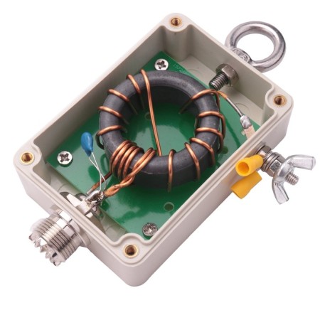
The high "Q" coil
The coil plays a fundamental role in impedance matching and maximum RF transfer. Its shape, given by the length/diameter ratio, the pitch between the turns, the material and diameter of the wire and the presence or absence of metal cores inside it, determine its quality factor “Q” (“Q” = Quality factor).
In simple terms, the higher the “Q” of the coil, the lower the high frequency losses. We have built a generously sized coil suspended in air without metal cores, with an L/D ratio of 1.3 and widely spaced turns, obtaining a “Q” value of about 2500 at a frequency of 28MHz, when the best competing antennas do not reach 1500.
This translates into maximum efficiency, and the ability to handle high RF power. In addition, the coil is directly connected to DC-Ground, so atmospheric disturbances and background noise are significantly reduced.
The UHF Connector
The FE10V connector is not a commercial SO-239 type as used by most manufacturers. The connector was designed and manufactured directly by us, has a real impedance of 50 Ohm and is usable up to 500MHz. The goal was to make a reliable connector capable of withstanding 5Kw CW continuous at 30MHz.
The body is made of nickel-plated CW614N brass, while the pin is plated in 24K gold to avoid oxidation and is equipped with a 4-fin insulator that maintains its centering and elasticity, avoiding contact losses.
The insulating part is made of PTFE, one of the best insulating materials for its exceptional electrical (low dielectric constant, and low loss factor) and thermal (operating temperature from -100° to +260°) properties. Finally, the connector is protected by a special elastomer cap that prevents water and humidity infiltration.
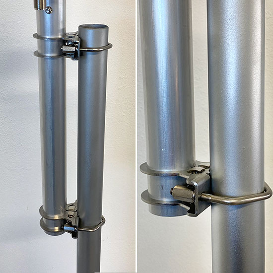
The Anchor Bracket
Made of 2.5 mm thick AISI304 stainless steel, it is fixed to the antenna tube using a clamp locking system, creating an extremely robust mechanical lock.
The fixing to the mast is made with M6 V-Bolts in AISI304 and column nuts to facilitate tightening.
Warning: file_exists(): open_basedir restriction in effect. File(/views/templates/hook/posproductcomments.tpl) is not within the allowed path(s): (/home/fhamradi/:/opt/cpanel/ea-php81/root/usr:/usr/local/lib/php:/tmp:/etc/pki/tls/certs/ca-bundle.crt:/var/cpanel/php/sessions:/usr/local/bin/wp) in /home/fhamradi/public_html/classes/module/Module.php on line 2292


 No review at the moment