- Out-of-Stock


Ref: vvinterface
Out-of-Stock No review at the moment

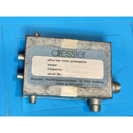
The DRESSLER Preamplifier Interface | VV-IRTERFACE
Allows remote switching and powering of pole-mounted preamplifiers via the coaxial power cable.
It also provides delayed switching via internal relay
for a power amplifier. |
The information for the transmit-receive switching can be provided
to the VW INTERFACE in two different modes:
from the push-to-talk (DTT) line of the transceiver
or via a positive switching signal taken from the
transceiver
In all cases, the VV INTERFACE connects to the system at the point closest to the antenna
in practice between the transceiver and the coaxial power cable or between the power amplifier and the coaxial cable. { The system configuration is shown in figures 3 and 4 for the cases without and with power amplifier}.
In receive mode, power is supplied to the preamplifier via the coaxial cable. In transmit, this power source is connected digitally via the internal circuitry.
DC power to the system is via the Phono connector at connector 1 (see figure 1).
The center pin is positive (+) and the shield negative (=).
The pole mounted preamplifier must have a supply voltage of at least 12 volts DC. This means that the supply to the VW interface must be greater than T2 Volts to allow for voltage drop in the coax cable. The actual safety margin depends on the cable resistance, typically a minimum of 1-2 volts per 25 meters of READ is expected. ar AG213/U
Transmit/receive switching can be done in two ways:
+ PTT
Using the phono connector 2 {figure 1 | connect the center pin to ground
to select the transmission mode,
{Connect the center pin to the shield = Cabinet = ground}
DC volts in PDM mode are available from the transceiver and can be fed to the center pin of the phono connector
Some Tame. {figure 1}.
{The negative of the oo switch connects to the shield
of the phono connector = ground}
When using a power amplifier, it is best that it is 14-25
after the PERNA LE can already be switched. This can
be possible if the amplifier has a separate Push-to-Talk input
r/t-wifi, using the phono contactor output
A" {figure 13}. The center connector is grounded
on the case approximately 0.8 seconds after switching the transceiver and preamplifier.
In case of accidental short circuit of the coaxial power cable, protection is provided by an internal fuse [0.7 A] located
on the printed circuit board. If no DC voltage appears on the
coaxial output connector (in Yecelve mode), check the
fuse. Access to the fuse is obtained by removing the 110
from the case.
—WARNING 1!!!
When applying continuous power to the VV interface, it is absolutely
It is vital that the transmitter (transceiver) is fully powered
when push-to-talk (PTT) connections have been made
to the YV interface. Otherwise, the RF power will destroy the
RF preamplifier transistor because the internal relays
will not be switched.
In this case there is no warranty. If the preamplifier does not work, disconnect the power from the VW interface on the phono connector 1 and leave the control lines [PTT or switching voltage].
TECHNICAL DATA
OPERATING FREQUENCY RANGE 100 → 500 MHA?
INSERTION LOSSES 0.5 dBs typ. max.
OPERATING VOLTAGE 12 ... 18 Volts max,
CURRENT at 0.3 Ampere
TRANSMISSION/RECEPTION SWITCHING STEP to ground or positive
SWITCHING VOLTAGE SWITCHING VOLTAGE LEVEL +6 + +12 Volts DC
RF CONNECTORS ti connector (or 507239)
FIGURE 1 W INTERFACE CONNECTORS
1 SUPPLY VOLTAGE
andL
DIT Vy. J interface
| { |
(top view) THE
6 FIER
30 COAXIAL POWER SUPPLY)
POSITIVE — .
SWITCHING. Ll =
RELAY OUTPUT
VOLTAGE ? FOR EXTERNAL AMPLIFIER |
M SOCKET FOR
TRANSMITTER OR PA
FIGURE 2 WIRING DIAGRAM
FIGURE 3
INTERFACE AND TRANSMITTER WIRING
DIET
PEE
PREAMPLIFIER
PTT E =
TRAISCENVER |—] | W INTERFACE | Ре;
| TR
J COAXIAL CABLE SWITCH
| TENSION
COAXIAL CABLE
FIGURE 4 "and
WIQIIS or TRANSMITTER - POWER AMPLIFIER = =
AND MY-PREAMP INTERFACE
POWER SUPPLY
PTT DR SWITCHING POWER SUPPLY
| | POKER AMPL, AND
| WW INTERFACE TRANSCEIVER
The
PTI to
§
|
PTT CONTROL TO PA
COAXIAL CABLE
Subject to change without notice.
MADE IN W-CERMANY BY
aresler
high frequency technology gmbh
WURSELENER STHASSE 7
C5180 STOLBERGAGERMANY
TEL 62402 51 22
Data sheet