


Ref: IC7760Anniversary

 No review at the moment
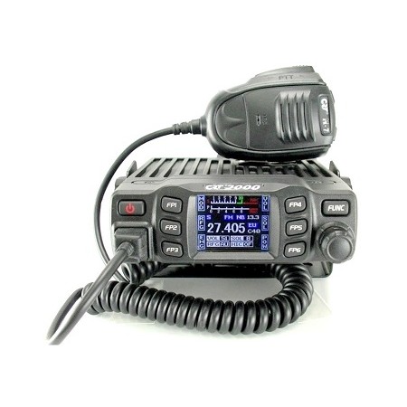
Superior Class HF/50 MHz All Mode Transceiver

High power and clean transmission signal for great strength in contests and DX hunting
Superior HF/50 MHz All Mode Transceiver

In today's connected world, the IC-7760 introduces a new connected system consisting of a remote control head and an RF bridge, connected to a commercially available control cable (LAN). This concept increases the flexibility of station installation, freeing up more desktop space by placing the RF bridge in an area closer to the antenna feed point. In addition to the direct connection function, the control head to the RF bridge, uses the home network to make any tabletop and a PC is not necessary!
The IC-7760 consists of a separate remote control head and RF bridge, and uses a LAN cable to connect between them. It increases installation flexibility. A control cable (3 m, 9.8 ft) is supplied with the transceiver, and a commercially available LAN cable* can be used to install the RF bridge in a more remote location. It allows the RF deck to be placed in a rack or other location away from the station desktop, providing a quiet cabin environment away from the noise of the fan used to dissipate heat generated by the RF bridge.
* LAN cable: Cat5e or above. Cable length: Maximum 100m, 328ft

The IC-7760 can be connected to the control head and RF bridge via a wired home LAN network*.
This gives the user even more flexibility than the RF deck. Because of its simple setup that does not require a PC,
The 7760 control head can be moved anywhere in the house and operated not only from the shed but also from the living room, etc., as long as a LAN connection is available.
* Communication between the control head and the RF deck depends on the network environment it is used in. Gigabit Ethernet is required.
The control head can be used on a different network segment than the RF deck, for example via a network switch.
The IC-7760 has independent MAIN/SUB receivers, from antenna to speaker, so that one receiver section has no effect on the other, providing simultaneous reception of two signals in different bands/devices with identical performance.

As with the IC-7851, the two spectrum scopes provide simultaneous display of the MAIN and SUB bands allowing the operator to see band change conditions.
The IC-7760 adopts the RF direct sampling system, in which RF signals are directly converted to digital signals and the signals are processed by an FPGA (Field Programmable Gate Array). This system avoids nonlinear distortions that occur in the mixer stages during analog signal processing. Furthermore, by using DSP units in both the RF bridge and the control head, the IC-7760 can handle complex audio path switching thanks to various interface inputs and outputs, minimizing delay in a home LAN environment.
 |
Block diagram overview |
|
The DIGI-SEL (Digital Pre-selector) is highly effective in rejecting strong out-of-band signals, such as from broadcast stations or multi-multi operation. In conventional models (such as the IC-7850/51 or IC-7610), the DIGI-SEL circuit was positioned immediately after the RF input (antenna) to prevent signal distortion from out-of-band interference. Even if the preamplifier was turned on, the noise figure (sensitivity of the receivers) could not be improved, since DIGI-SEL had insertion loss due to its narrow bandwidth. In the IC-7760, which is a direct sampling system, DIGI-SEL prevents overshoot (OVF) due to unwanted out-of-band signals rather than signal distortion, and the preamplifier uses the A/D converter to take full advantage of its dynamic range. When the preamplifier is turned on in the IC-7760, the preamplifier first improves the intended signal, and then DIGI-SEL filters out unwanted out-of-band signals. This makes it possible for the preamplifier to work in conjunction with DIGI-SEL.
 |
 |
While the previous model covered the HF bands with a BPF (Band Pass Filter), the IC-7760 uses a separate 11-band BPF in the HF bands.
Additionally, by using specialized sharp filters for each amateur band, the BPF efficiently attenuates out-of-band interfering signals in the RF stage and prevents overflow at the A/D converter. 
 |
|
The DPD function corrects nonlinear distortion at the power amplifier by applying reverse distortion in advance. Clean signal transmission is achieved while delivering 200 W of high-power output. The DPD function also works at 1 kW output in combination with the IC-PW2*.
DPD OPC-2501 feedback cable is required when using with IC-PW2.
DPD OFF |
DPD ON
|
|
Signal received on IC-7300 |
|
* 200W and 1 hour continuous transmission with 100V AC input (at room temperature 25 oC.)
|
PA unit with a large heat sink |
Efficient cooling system with four fans |
Automatic antenna tuner
The IC-7760 incorporates a mechanical relay internal antenna tuner as a first for our 200W models. It provides faster tuning than the conventional variable capacitor type. Once tuned, the corresponding information is automatically recalled for the next frequency, facilitating smooth band changes and multi-band operation.

Antenna tuner unit
The IC-7760 control head has dual main and sub displays. The displays are a 7-inch wide main display (800 x 480 pixels, WVGA) and a 2.4-inch sub display (320 x 240 pixels), and both displays are touch screens. The main display shows information necessary for operation, including the MAIN/SUB operating frequencies, the setting/time status of each function, as well as the spectrum scope, application scope, S-parameter, and RTTY/PSK31/63 decode messages.

Meter setup example
The 2.4-inch sub display can show filter settings, various meters and a band stacking register. The filter setting screen can display the IF filter passband width and IF filter shape superimposed on the IF filter passband signal. This function shows visible images of twin PBTs, manual notch effects. The improved visibility of information improves operability and ensures smoother operation.
|
Example of filter effects |
Example of various meters (S/Power, ALC, COMP, SWR, Id) |
Band stacking log |
The Dual Spectrum Scope provides excellent scanning speed, resolution and a wide dynamic range of 100dB with combined FPGA, DSP and CPU processing for the main and sub bands. It can also monitor two different bands at the same time, useful for condition monitoring and during contests. The dual scopes can be displayed by the left-to-right or top-to-bottom layout, depending on the situation and needs. In continuous SCROLL mode, a wide bandwidth of more than 1MHz can be seen on the scope screen. The waterfall display shows changes in the frequency spectrum vertically, allowing the user to find a weak signal that is difficult to detect with the spectrum scope. Increase your QSO chances without missing the weak stations
|
Left-to-Right Dual Scope Example |
Example of a zoomed waterfall exposure |
Example of top-to-bottom double scope |
The Audio application screen displays the frequency components of the transmit and receive signal on the FFT scope and its waveform components on the oscilloscope. The Audio scope makes it easy to monitor signal characteristics such as microphone compressor level, filter width, and notch filter. You can monitor the received CW keying waveforms on the oscilloscope.
|
Audio Scope Example |
CW Keying Form Example |
The IC-7760 is also equipped with dual speakers. By separating the MAIN/SUB audio into the left and right speakers respectively, audio distinction during Dualwatch operation is improved.

Data sheet
Specific References